
The Ferrari 360 Spider Wind Stops, which are little screened frames that sit behind the cockpit and block the wind from messing up the driver's and passenger's hair, have custom gaskets to hold in and stretch a fine mesh screen. If the gaskets are deteriorated, the typical solution is to buy the entire frame with the gasket and screen. The gaskets are unavailable through Ferrari or any aftermarket that I could find. I decided to try and change that.
The steps involved in this project:
- Procure a set of used wind stops.
- Reverse engineer and improve the gaskets for the wind stops using Fusion 360.
- Create a raw plug (the thing that the mold is made around) using a 3D printer.
- Finish the top surface of the plug to be rounded and shiny as possible.
- Create a two part silicone mold from the plug.
- Cast a urethane rubber finished part from the silicone mold.
- Test the finished piece and evaluate the results.
Procure a Set
Here's the set of wind stops I purchased.

The two side frames are bare but the middle frame has both a gasket and a screen. The screen's ripped in a couple of places and the gasket is worn and brittle.
While the gaskets on my 360 Spider look pretty good, they are stiff and will probably start cracking soon enough.
Reverse Engineer
The gasket has a tab that fits into a slot on the frame that traps the screen between the tab and the frame slot, holding it securely and stretching the screen very tight. The gasket is pretty consistent along the entire length but has an area at the bottom that's thinner which is used as a weather seal between the car and the wind stop.Here's the tracing.

The first couple of iterations consisted of just 3D printing the part that inserts into the frame. One thing about 3D printing. It's slow. For testing purposes, the best strategy is to print the absolute minimum. Once the shape evolved, I printed the entire part, did some fit checks and after a bunch of iterations, I had a good shape.
Here's a pile of "iterations" from the 3D printer.

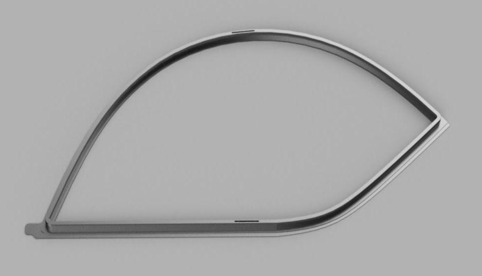
Create a Raw Plug
The gasket is printed upside down with the outward face, the top of the gasket, printed at the surface. This causes the top surface, the surface that shows on the car, to be completely flat, with sharp edges. To make a decent top surface, the PLA plastic used to make the plug has to be finished to a rounded, shiny and smooth surface.
Since the plug is quite large, about fourteen inches at the widest point, it has to be cut in pieces to be printed, then glued back together before moving to the next step. Cutting the model into printable size pieces is done in the slicer program.
The plug is printed as two pieces with the join right in the middle.
Here's a picture of the final version a plug being 3D printed.

I did some research on gluing PLA and the consensus is to use super glue of some sort. I have about a dozen different super glues and tested them all to see which did the best. The result: They all sucked. The problem is not really the glue. It's the small contact area. The result is a weak bond that breaks very easily.
The solution is to add a biscuit to the joint so that actual plastic is making the joint strong and not a glue surface. A biscuit in woodworking is a butt joint made with a thin and strong piece of wood, sort of like the silhouette of a football in shape, that fits into a slot cut by a special machine on both sides of the butt joint. The biscuit increases the strength of the joint by the strength of the biscuit. I used the same principle to join the sides of the plug together, using Loctite Gel Super Glue. The slots can be seen in the rendering above. The biscuit printed along with the plug.
Here's the biscuit joint close up.

Finish the Top Surface
I needed a fixture to hold the plug securely while I finished the top surface.
I use a program called Aspire to design and create cut files for my CNC machine. To use a Fusion 360 drawing in Aspire, the drawing has to be exported in DXF format, then imported into Aspire, toolpathed, and cut files exported for the CNC.
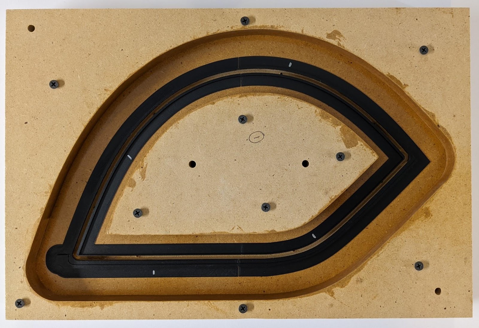
Here's a picture of the fixture, cut from MDF, and sealed with an epoxy (West Systems) clear coat along with the 3D printed plug. The MDF has to be sealed for wet sanding. MDF and water mix way too well.

With the plug mounted in the fixture, I sanded the top surface with 80 grit to shape, then 120, 220, 320, and finally 800. The printing texture was still visible at this point.
Here are the three plugs and their fixtures sanded to 800.

To fill in and cover the texture, plus give a good, solid base, the plugs were primed with a rattle can (Dupli-Color DAP1690), then sanded with 800 grit until the black color showed through, then primed again and sanded lightly with 1500 to remove any surface defects. I didn't bother with a color coat as the primer surface after sanding was very nice.
The final coat is an automotive two part clear coat (Acme) that is easy to spray and buffs out to a very nice shine. I used a buffing wheel on my drill press along with a 3M compound cream to bring out the shine.
One thing I learned is that sanding on the PLA should stop at 220 grit and be primed. PLA can be shaped by sanding but due to the defects built into the material, seems to require coating to produce a reasonable surface.
Finished plugs.

Create a two part silicone mold
YouTube is a great resource for learning how to do something unfamiliar. In searching the web for information on making silicone molds, I found a really helpful video from a company called "BJB Enterprises". They sell molding supplies and all sorts of interesting stuff.Here's a link to the first part: How to make 2-Part Silicone Mold
The process seemed well documented and they didn't skip over anything important. BJB's video was so good I bought all the supplies I needed from them.
The mold requires a mold box to hold the liquid silicone until it sets, and that mold box can also be used to stabilize the mold when casting parts. According to what I learned about molds, a mold should have at least three quarters of an inch of silicone between the plug and the mold box.
I went back to Aspire and used the same drawings to make a mold box by creating an offset design with an inch of mold space instead of three quarters. Better to have too much than too little.
I cut the mold box using my CNC machine and MDF. Silicone is expensive and difficult to mix so minimizing the amount of silicone required for the mold would be a good engineering thing.
Here's one of the mold boxes being cut out on the CNC.

Here's the stacked mold box. Any surface that touches silicone is to be coated with epoxy, sanded and then waxed with an industrial mold release wax.

One complication with the gasket is that it has two thicknesses on the backside of the gasket. The thinner part is a water seal that keeps water from flowing from the engine area behind the cockpit into the electronics bay which is right below the roll bar. When mounted, this thinner area contacts the metal part of the car and bends to form a seal. That's why it's thinner.
Here's the cross section of the plug.

The spacer was modeled using Fusion 360 by creating an offset, just like I did in Aspire to make the mold boxes, then 3D printed. The spacer had to fit snugly to the mold so that silicone wouldn't creep under it and cause a problem. I used epoxy to glue the spacer to the mold.
All the contact surfaces of the MDF material are coated with epoxy in this picture. The plug snaps into the slot, exposing only the top surface to the first part of the mold. To get the plug out of this tightly fitting spot, holes were drilled in the back of the mold base board for screws that when tightened, gently forced the plug out of the slot.
Here's the mold with the spacer mounted in the base board of the mold. The screw holes to force out the plug can be seen in the slot.
Before the plug was installed in the base board, it needed to be sprayed with a mold release agent. I used one supplied by BJB enterprises for just this use.

The silicone I used for this mold is BJB Enterprises 5041 Shore 40 A. The "Shore 40 A" is a measure of hardness, or the resistance of the material to indention. Shore 40 A is easy to push a fingernail into. The higher the Shore number, the harder the material. The A scale (as in 40 A) is for softer rubbers.
To determine how much silicone would be required, I used the scrap of wood left over from making the mold box, the chunk between the inside and the outside pieces. This chunk of scrap would have the volume of the mold box (plus the kerf from an eighth inch end mill). To get the volume, it is placed in a plastic bag and dunked into an absolutely full pot of water. After the water settles, the bag is removed from the water. The drop in level is the volume of the bag with the mold box scrap. Refilling the pot to overflow measures the volume needed. Using the density data provided by the manufacturer of the silicone, I calculated it needed a bit over a kilogram of silicone. The silicone is measured for mixing by weight, not volume, which is why I needed to know the weight.
Silicone was mixed, degassed and poured in the mold box with the base board in three batches. The working time of the silicone is about an hour. Each successive batch was poured in such a way so that the first batch was always on the leading edge. If a later batch overtook the leading edge of the silicone as it slowly oozed its way across the mold, an air pocket could be formed, ruining the mold. I used one kilogram of silicone and it almost filled the mold. I wanted to leave a small amount of space at the top for the next level.
An interesting part of this process is the degassing of the materials. Degassing involves taking the mixed material, placing it in a vacuum chamber and then pumping as much air out of the chamber as possible. During the process, air bubbles in the mixture go from tiny, itsy bitsy little bubbles into bubbles the size of a grape. The bubbles rise to the top of the mixture and pop, leaving behind a smooth bubble free mixture. Bubbles in the mix cause voids, which can destroy a mold.
Degassing takes about five minutes using a <25 micron, 5 CFM vacuum pump. The chamber is just a large aluminum pot with a thick glass cap and a silicone gasket to seal it. The chamber has a gauge and a couple of valves to control the vacuum. It's mesmerizing to watch the mixture rise slowly, start bubbling and then eventually collapse back to the original volume when the bubbles are purged.
Here's the vacuum pump I used. It's about $125 on Amazon.

This pump doesn't come with a filter on the output port. An oil filled vacuum pump puts out a significant amount of oil mist which has to be dealt with by either capturing it or venting outside. I found a mist filter on eBay for another, much more expensive pump (Genuine Busch Vacuum Pump Exhaust Filter) and 3D printed an interface piece (shiny black thing below the filter) that allowed me to run the good filter on my cheapo pump. It worked perfectly.
In the background is the vacuum chamber. It's a bit big for my application. Normally, bigger is better but in this case, bigger means a longer time to draw down to a vacuum. If I had to do it again, I'd buy the smaller chamber and save about a minute in the degassing process. Time is important because these materials have a limited work time so moving along quickly is a good idea.
After the bottom of the mold has set, the base board is removed using the screws that push the plug out. The mold separated easily from the baseboard and the mold box. The plug remained in the bottom of the mold as planned.
I decided to make the vent and fill tubes instead of buying them from BJB. These are just pieces of acrylic rods with a sharp twenty degree cone on one end. I could make these myself quite easily on my lathe and in the process, use that very nice piece of equipment (Grizzly G0602).
Here's a picture of one of the vent tubes in the lathe. Vent tubes are 0.23" which just happens to be the exact outside diameter of a common drinking straw. The fill tube is 0.5".


The fill tube should be located at the bottom of the mold with vents in strategic places where air might get trapped. I went a bit overboard perhaps with vents but it is impossible to add a vent after the mold has been made.
The vents are superglued to the plug very carefully. The amount of surface area being glued is very small, about the size of a worn pencil tip. As the urethane liquid moves through the mold, it also moves up the vent, carrying away any bubbles and allowing the urethane to completely fill the mold. Voids in the mold equal a failed casting so it's critical to vent any area that can trap air.
The instructions in the video have the vents glued directly to the surface of the plug. I found this to be so weak and fragile that I knocked several of them off just assembling the mold. I found that a much better way to attach the vents and fill port is to use a twenty degree pointy Dremel bit, make a small cone shaped hole in the plug and then glue in a pointy vent. This provides a much sturdier construction but damages the plug. For my purposes, the plug damage is irrelevant.
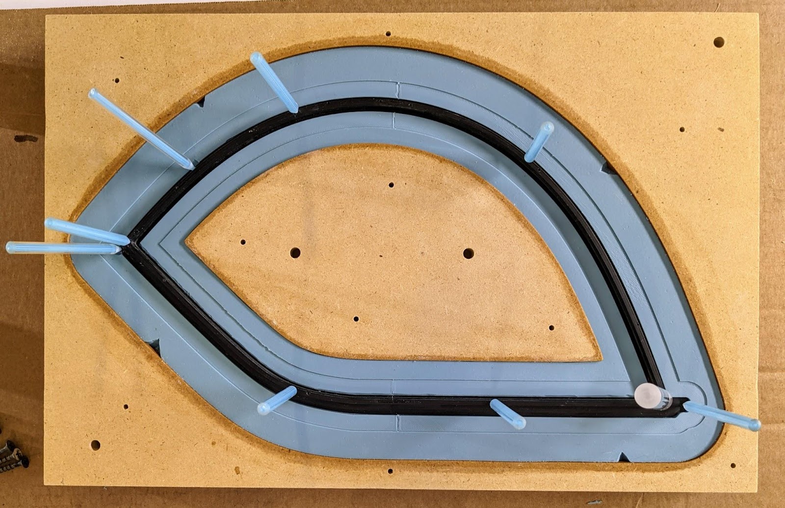
Here's a picture of the plug cast into the bottom of the mold with the vents attached. Note the indentations in the mold from the spacer piece. All the vents and the fill tube are on the bottom of the plug. Nothing will show on the top surface. The little knicks in the edges of the mold will create keys that allow precise alignment of the top and bottom parts.
After the vents and fill tubes are added, the mold box is assembled and screwed down. The interior of the mold is coated with a mold release for silicone. It's a very light oil. Care should be taken to coat all corners and inside edges with a brush (spray the can onto a flat surface to get some liquid) to be sure the mold will come apart easily.
After the mold release has dried (a few minutes), the bottom is blown out with an air gun to remove any little bits and it's ready for the top pour.
This is what the mold looked like right after the top was poured. It takes about eight hours for the silicone to set.

The vents and fill tubes are removed with a pair of pliers. Just grab and twist. The superglue on the plug gives up easily and since silicone really only sticks to itself, even without a mold release, the rods should come out quite easily. I sprayed mold release on them before the pour so they came out with a slight twist and pull.
With the proper use of mold release, the two halves of the mold should separate easily, leaving the plug in one side. Since the top of this mold had the tab and the bottom was just the top surface, the plug stayed in the top of the mold. The plug pulled out of the bottom very easily.
Cast a urethane rubber finished part
Before the liquid urethane can be poured, vents and a fill tube are installed. The vents are made from common drinking straws that can be found virtually anywhere. They fit exactly in the hole made by the acrylic 0.23" rod. To get them into the mold, a little mold wax is applied to the end, then carefully twisted into the vent hole about half an inch.The fill tube is made from a standard transparency sheet that is usually used for presentations. The sheet is rolled up into a sharp cone, with about an inch and a half to two inch diameter at the top and about a quarter of an inch at the bottom. Tape secures the cone. The end is cut so that it fits into the fill hole and then wiggled down a bit more. I 3D printed a brace for the fill tube so that it wouldn't accidentally tip over and make a huge mess.
Here's the completed mold ready for the pour. Note the little blocks tilting the mold so that one end is low and the other is high.

I just guessed at the volume needed for the mold at four hundred grams. Seemed like a lot for such a thin piece of trim but better to have extra than run out.
The first pour I used BJB Enterprises L-3540 Shore 40 A soft urethane which has a working time of twenty-five minutes and a viscosity of 1600. It's a lot more liquidy than the silicone but it has to flow into a very small hole and around a long and thin path to move all the way through the mold before the work time is up. The mixture starts to set after the work time has passed and once it starts to gel, it's not going to fill any more of the mold.
The urethane mixture requires degassing like the silicone. Degassing was faster with the urethane than mixed silicone, probably because of the lower viscosity of the urethane (the silicone I used had a viscosity of 26000 vs. 1600 for the urethane mix).
A quirk of urethane is that it can be destroyed quickly if moisture gets into the container. To protect the unused urethane, a blanket of dry air has to be blown into the container before sealing the can. The "dry air" can be purchased in an aerosol can for about $15, or if you just happen to have a tank of pure nitrogen with an air gun attachment, that works too.
Here's my fancy can of dry air. I ran it at about five psi and blew the inside of the can for ten seconds to purge it.

A less wasteful solution would be to use a half inch plastic tube and a funnel. The risk in doing it this way is that the solidified urethane might be difficult to remove from the plastic tube and it would be a waste item. The cost of the tube is low and the cost of urethane is high so using a funnel would probably be more efficient from a materials standpoint.
As the urethane flows through the mold, it also flows up the vents. The progress of the pour can be easily seen by monitoring the height of the urethane in the vent tubes.
Here's a finished pour. All vent tubes show black material, indicating a full mold.

After the demold time passes, the vents and fill tubes are twisted off and the mold can be opened. I got a bit chicken and waited twenty four hours before opening the mold the first time. Perhaps a bit afraid of what I'd find.
Amazingly enough, the very first casting came out perfect. No voids, no leaks and very little touch labor to finish the part. The Shore 40 A rubber seemed a bit too soft though. I did a second casting with Shore 60 A and the results were much better. It takes a few days for the urethane to completely set so I left it to cure.
Here's the Shore 60 A version after cracking open the mold. Note the seepage in this casting. This stuff is very thin and just rubs off. The surface quality is excellent.

Here's the Shore 60 A version fresh out of the mold. No cleanup yet.

Test the Finished Piece
After the rubber finished curing, I installed the gasket into the frame with a screen.The gasket with the screen fit tightly and took about ten minutes of slowly circling around the frame with my thumbs, easing the gasket into the slot as the screen became taut. When the gasket had about a sixteenth of an inch left, the excess screen was trimmed away using a snap blade knife. To finish the job, the screen was turned face down and the back of the frame was pressed into the table, giving the gasket even pressure to fully engage.
Here's what it looks like finished.

The original screen in the Spider is a soft nylon or polyester (or ?) 30 x 50 mesh knit that seems to be unobtainable. I'm looking at other possible materials that can come closer to OEM.
Conclusion
This project taught me a number of important skills that I'll be needing for my other project. It also gave me the confidence that I can produce those parts just like I did these gaskets.I'm sure that many cars, boats and other things exposed to weather have gaskets made of unobtainium. For those seeking an alternative source for their disintegrating gaskets and seals, this is absolutely a viable method of reproducing them.
I still have a few questions that I'll answer here if I can.
1. What's the working temperature range of the cured urethane?
2. What steps, beyond adding BJB's UV-100 to the mix, can I do to keep the cured black urethane from deteriorating in the sun?
3. Are there any recommended surface coatings for weather resistance?
4. What kind of life expectancy can I see in an automotive application?
5. Is there a better choice for casting automotive trim than L-3580 REV 1?
Simply amazing work! Details matter!
ReplyDeleteWOW, thank you for documenting, what an unbelievable effort
ReplyDelete